
| BASICS OF SURVEY |

Notions on architectural survey with total station.
This page shows some general notions relating to the surveys with total station, which will be used to better understand the results of the activities of this type, which took place in Pierle.
The term architectural survey refers to a series of operations that allow to measure a building. The product obtained at the end of the work is a representation, that is a scale drawing, of the object in question. This can be done in different ways and using different measuring devices.
In any case, this activity is divided into several distinct operations:
- Inspection
- In this first phase, the structure is inspected in order to determine the most suitable technique for the survey and a classification of the architectural elements is carried out.
- The perimeter and coverage of the area to be surveyed are determined and the survey methods are determined
- Schematic - Preventive breakdown of the object to be measured
- the complex to be detected is divided into homogeneous and measurable elements. The floors, the rooms, the elevations, the sections that make up the meaning of the model are identified ....
- The program of the stations is drawn up of measurement. The survey is divided into stations. For each station a point of origin is chosen and points are measured. The measurements performed are all taken with respect to the origin. The measurements of the stations are brought together for the overall restutition of the architectural complex.
- Geometric sampling - Measurement of the building
- Photographic sampling - Photographic coverage
- Three-dimensional rendering - Computerized representation
- Layout and printing
In this article we will deal with the Geometric Picking activity performed with a
indirect measurement called total station.
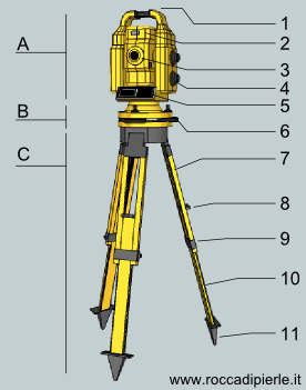
The figure to the side shows the schematization of a total station. Three main parts can be identified:
A) Head
B) Base
C) Tripod
List of the most relevant parts of the device:
1) Handle
2) Alidada
3 ) Telescope
4) Micrometric adjustments
5) Computer
6) Bubble adjustment screws
7) Fixed leg
8) Sliding leg head
9) Tripod screw
10 ) Sliding leg
11) Foot to Toe
The measurement phase is divided into stations. For each of them it is necessary to perform stationing . With this term we intend to specify a whole series of operations to be carried out before being able to carry out the actual measurement. Stationing consists in leveling the head of the station, i.e. making sure that the vertical axis of the upper part is perfectly vertical. To obtain this condition, the upper face of the Base (B) must be perfectly horizontal.
First of all, place the tripod on the ground by placing a first leg on the ground, pressing it on the foot (11) or on the head (8) of the moving part (10). Once the first leg is placed, the second and third are also planted in order to have the upper face already quite level. If so, the locking screws (9) will be closed.
By placing the base, it is possible to evaluate the flatness through the air bubble indicator on it. The base screws allow you to correct slight errors. At the end of this phase, the head (a) of the station is positioned above the base by lifting it by acting on the special handle (1). The criticality of this operation is dictated both by the weight of the instrument and by its extreme fragility. The internal parts of the optics of the instrument are very sensitive to vibrations and make it critically vulnerable to shocks.
Once the placement is complete, the instrument is switched on and it immediately checks the verticality of the axis and its centrality with respect to the base. If this check fails, the station stops in the sense that it will not perform any measurement since the parking phase has not been performed correctly.
If the check is successful, the instrument can be initialized by setting the height from the ground and the zeroing angles.
The physical positioning point is often defined on the ground by means of real nails which are driven into the ground, in order to be able to repeat the stationing.
In this phase it is also possible to zero (place the zero origin of the station) using GPS devices to have a very useful geolocalized position during the processing phase on the computer.
To detect an architectural detail it is therefore necessary to perform a stationing. The choice of the most appropriate point is carried out during the inspection phase and must be conducted in such a way as to ensure the subsequent overlapping of the point clouds obtained in the nearby stations.
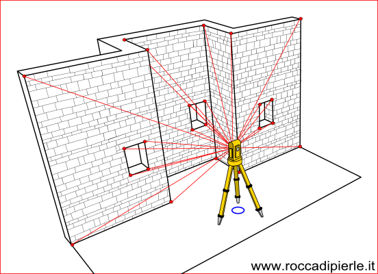
The measurement is performed by illuminating the points to be measured with the laser beam emerging from the objective. This beam allows reading without additional pointing devices, acting directly on the walls to be detected. The computer, for each reading, measures the two azimuth and zenith angles and the distance of the point, calculating the coordinates of the measured point and writing it into the device's memory.
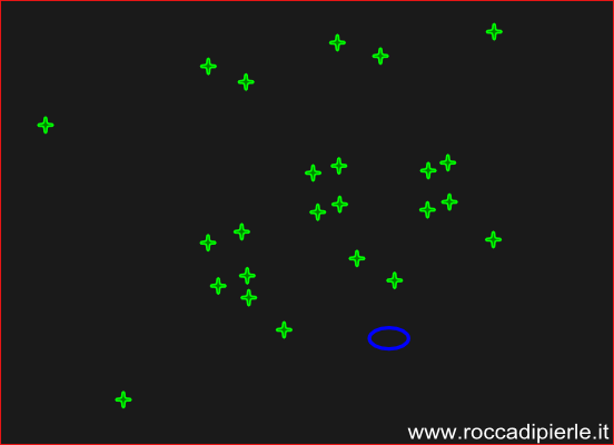
The next step is to transfer the measured points from the station memory to that of a computer. This can be done later when they have been stored all the stations. A special software allows to represent the points in a Cartesian space together with the reference
(blue circle) of the zero of each station.
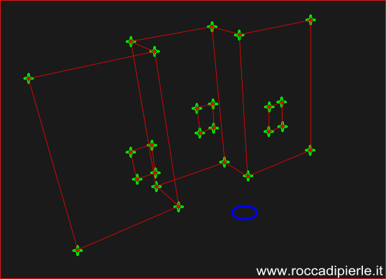
The point cloud consisting of the points measured at each station is unclear without the addition of geometric elements that facilitate visual interpretation. This can be done on the computer manually selecting points or using surface recognition software. The second way is often used with very large point clouds where manual selection would be prohibitive.
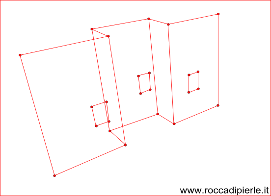
Whenever possible, surfaces are added together with line segments
fictitious, that is, imaginary that reproduce the masonry parameter in an approximate way. These tools
geometric allow to give geometric meaning to the graphic representation. Indeed, it becomes possible
manipulate geometry by giving depth to architectural elements. In this way elevations and sections can be created
distinguishing the points placed at different depths.
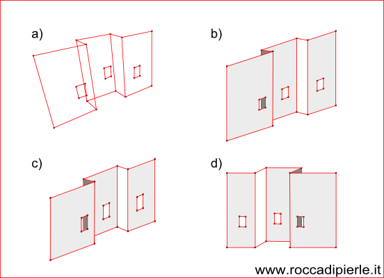
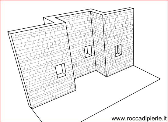
The previous figure shows the advantages of adding surfaces. In figure a) is
represented the model limited to segments. The meaning of the walls is unclear because the lines
in the foreground they intersect with the following ones. Figure b) which presents the plans that delimit the parameters
of the structure using plans is easier to read. The following figures show the representations of the model
by means of isometric axonometries (c) and cavaliera (d).
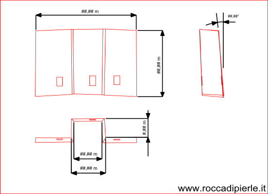
Finally, the surfaces obtained are suitable for measurement and comparisons that can be made directly
on the orthogonal projections performed on the three-dimensional restitution. These measurements can be useful for planning the interventions to be performed on the architectural structure, preparing scaffolding, preparing metric calculations, etc. etc.
This page has the modest purpose of giving a smattering of how architectural surveys are carried out,
in order to facilitate the understanding of the results of the survey phase that is being concluded in Pierle in this one
period.
Last update 14th March 2021
| 


