
| ARCHITECTURAL REPRESENTATIONS |

Architectural representations
15th April 2011 - The new three-dimensional cross-sections of the Rocca di Pierle obtained from the elaboration of the reliefs made with the scaffolding are almost ready. Since these are quite complex elaborations, it was decided to prepare a short guide to facilitate reading. This page summarizes some tables for the three-dimensional representation of a small tower that will serve as an example.
Note: The dimensions of the images on this page are quite large and may take some time to be fully downloaded.
On this page a tower is represented through a series of images. To represent a solid you can use, among other things: Views, Sections, Axonometries and Cross-sections. The VIEWS , as seen in the figure below, are Projections (orthogonal) on the main sides of the object, and generally give a two-dimensional (2D) view. You can therefore see a top view (fig. C) and the right view (fig.B), the left view (fig.D), the front view (fig.A) and the rear view (fig.E).
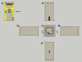
To show the internal parts of a hollow object, we must use SECTIONS . Sections are views that imagine cutting the object and eliminate some insignificant parts from the representation. The sections always appear cut imaginary parts of the object, which are highlighted with backgrounds (inclined parallel lines) or with bright colors (Yellow) that cannot be assimilated in any way to other real portions.
To define the Section (fig.F) a SECTION LINE AA is marked on one of the top views (in this case fig. C) of the model, showing arrows explaining the direction of observation of the dissected object.
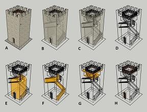
The AXONOMETRIES , on the other hand, allow a three-dimensional vision that is certainly more complete but necessarily more complex to achieve. Axonometries are representations that simultaneously show several sides of the same object. Using the TRANSPARENCY of the surfaces it is also possible to show the internal portions of the hollow objects.
Pure transparency, however, can make the model very confusing when too many lines are concentrated in the same points (see fig.D) . The INTERMEDIATE transparencies (fig.B and C) may however be insufficient to show side by side environments or details arranged one behind the other. where every detail is highlighted with a different color. In our case, the internal environment (fig.E), the stairs inside the wall (fig.F), the roof with walkway (fig.G) and the fixtures (fig.H) are highlighted.
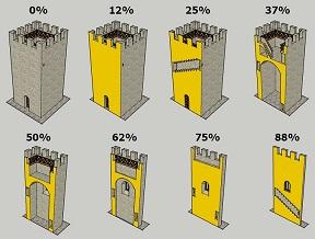
If imaginary cuts are applied to an axonometry (as to the sections for orthogonal views), the SPLITS are obtained. In models of this type, generally the portions of masonry that appear to be placed in view are colored with backgrounds (series of parallel lines placed at 45° with respect to the line of edges) or with pastel tones (ocher in our case). Very often the cuts of the cutaways are clean, and form orthogonal angles with respect to the planes of symmetry of the whole model.
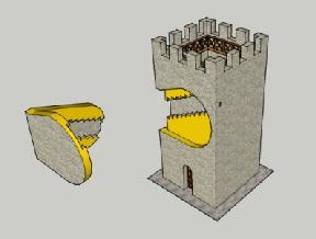
For more complex parts it is possible to perform SPLITS WITH FREE SECTION that is performed on surfaces other than planes or SPLITS WITH TEAR-OFF SECTIONS which are equivalent to eliminating only portions of the solid ( see figure below). In the cross-section of the Tower of Pierle, the latter is the only method to make people understand how the internal stopovers are made.
This small guide will therefore be useful when, during the explanation of the tower structure, they will be described from time to time the views and the Split sections of Pierle.
Last update 2nd August 2015
| 


